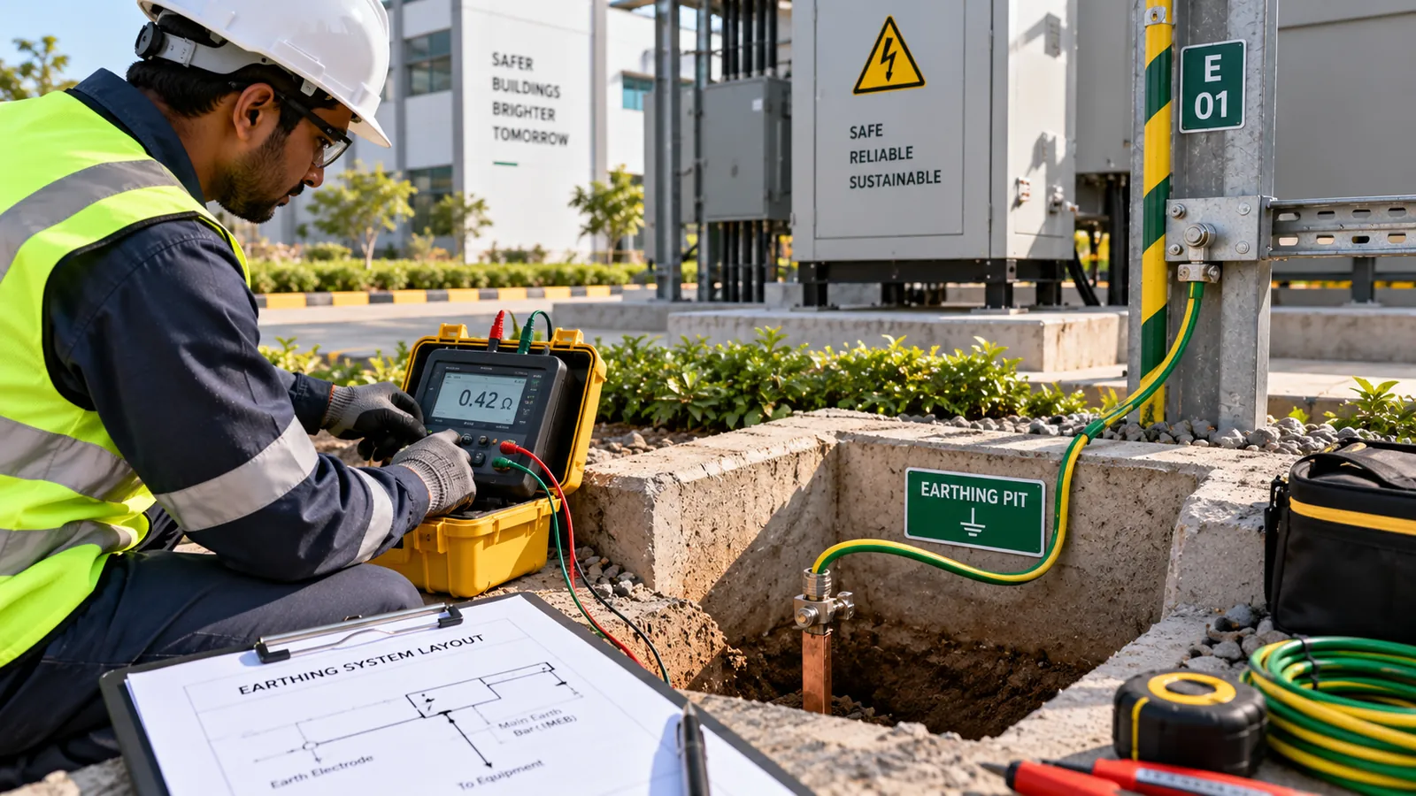
IS 3043 provides guidance for system earthing and protective earthing; it does not make one earth-resistance value universally correct for every commercial building. The required performance depends on the electrical system, protective devices, fault-current path, installation type and project or regulatory requirements.
Purpose and parts of an earthing system
System earthing connects a point of the electrical system, such as a neutral, to earth to control voltage and support protection. Protective earthing connects exposed conductive parts so a fault can be cleared and dangerous touch voltage limited. Equipotential bonding reduces voltage differences between conductive parts.
The complete path may include electrodes, earthing conductors, protective conductors, bonding conductors, terminals and joints. Earth continuity is as important as the electrode reading: a low electrode resistance does not help equipment whose protective conductor is broken or undersized.
What determines acceptable earth resistance?
The suitable value depends on system design, installation type, protective devices, fault-loop impedance or fault-current requirements, applicable regulations, supply authority conditions and project specifications. Different functions—such as a transformer neutral, equipment protection, lightning protection or sensitive systems—may need coordinated designs.
Soil resistivity, moisture, temperature, corrosion, electrode depth and spacing, parallel metallic paths and seasonal variation all affect a measurement. Adding electrodes without checking spacing, current distribution and bonding may give less improvement than expected.
Commercial-building design considerations
- Coordinate the supply earthing arrangement with transformer, generator, UPS, solar and transfer systems.
- Confirm automatic disconnection by the selected protective devices under credible faults.
- Bond structural metal, services and other required conductive parts.
- Provide durable, accessible test points and protect conductors and joints from damage and corrosion.
- Coordinate functional, protective and lightning-protection earthing without creating unsafe separation or circulating-current problems.
- Document electrode locations before they are buried and keep an updated single-line diagram.
Testing and maintenance
Testing may include continuity, electrode resistance, earth-fault loop impedance and protective-device verification, selected for the system. Use a suitable instrument and method, isolate or account for parallel paths, record soil and weather conditions, and follow safe isolation procedures.
Trend results rather than treating one reading as permanent. Inspect accessible joints, pits, labels, corrosion, mechanical protection and bonding after electrical alterations, excavation, lightning events or evidence of deterioration. A dry-season result can reveal conditions hidden by wet soil.
Practical assessment example
A commercial building records an electrode resistance that meets its project target, but a continuity test finds a loose protective conductor at a distribution board. The electrode value alone would have missed the hazardous fault path. The team repairs the joint, verifies torque and continuity, checks protective-device coordination and updates the maintenance record.
Judge the earthing system by the safety function of the complete fault path—not by one isolated “earth pit” number.
Using IS 3043 correctly
BIS identifies IS 3043:2018 as the Code of Practice for Earthing (Second Revision). This overview does not reproduce protected tables or clauses.
Source review date: July 28, 2026. Use the current official standard together with the applicable electricity rules, National Electrical Code, supply conditions, project documents and a qualified electrical engineer.
Frequently asked questions
What earth resistance does IS 3043 require for every commercial building?
There is no single value that is universally correct for every commercial building. The target must suit the system, protection, fault requirements and applicable project or regulatory criteria.
Is earth-electrode resistance the only required test?
No. Continuity, loop conditions, bonding and protective-device operation may also need verification depending on the system.
Why does earth resistance change by season?
Soil moisture and temperature affect resistivity, so readings can vary. Testing strategy should account for the credible worst condition and trend changes.
Related guidance and services
For site-specific support, see our commercial-building earthing assessment.